Ultrasonic Transducer Driver Amplifier Circuit

We have developed a portable high power ultrasound system with a very low output impedance amplifier circuit (less than 0.3 Ω) that can transfer more than 90% of the energy from a battery supply to the ultrasound transducer. The system can deliver therapeutic acoustical energy waves at lower voltages than those in conventional ultrasound systems because energy losses owing to a mismatched impedance are eliminated. The system can produce acoustic power outputs over the therapeutic range (greater then 50 W) from a PZT-4, 1.54 MHz, and 0.75 in diameter piezoelectric ceramic.
Rail Output Operational Amplifiers AD8541 General-Purpose CMOS Rail-to-Rail Amplifier ADP7104 20 V, 500 mA, Low Noise, CMOS LDO. Ultrasonic Distance Sensor (Simplified Schematic: All Connections and Decoupling Not Shown). Circuit Operation The ultrasonic ceramic transmitter is a 400ST160 made by Pro. I am looking for a circuit diagram for a high power ultrasonic amplifier.Needs to drive an underwater transducer rated at 50 watts.Currently using a single HexFet driving a 1:25 toroid to 1000vpp, but I need to increase the duty cycle past 1% for more output power.
It is lightweight, portable, and powered by a rechargeable battery. The portable therapeutic ultrasound unit has the potential to replace “plug-in” medical systems and rf amplifiers used in research.
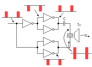
The system is capable of field service on its internal battery, making it especially useful for military, ambulatory, and remote medical applications. Driving circuit The circuit for the low-output-impedance driver is shown in Fig.
A pin driver (EL71581SZ, Intersil, Inc.) that is capable of driving high capacitive loads is supplied with a 5 V square wave TTL input at pin 3. The input timing signal comes from a 1.54 MHz crystal oscillator (SE1216-ND, Epson Toyocom, Inc.) that fits the ultrasound probe’s resonant frequency for maximum power transfer. Pins 1 and 8 are held at +12 V with 47 and 0.1 μF bypass capacitors to ground. Pin 2 is connected to pin 1 with a 10 kΩ resistor. Pins 4 through 6 are connected to earth ground.

Pin 7 of the pin driver is the output that provides a 12 V square wave to regulate the switching of the metal-organic-semiconductor field-effect transistors (MOSFETs) voltage drain. From pin 7 of the pin driver a 2.2 Ω resistor splits off with two 0.1 μF coupling capacitors into the input pins 2 and 4 of the low on resistance N∕ P channel MOSFET (IRF7350, International Rectifier, Inc.). Pins 1 and 3 of the MOSFET are held at a maximum of −50 and +50 V, respectively, with 820 Ω resistors across pins 1–2 and 3–4. A 47 μF and a 0.1 μF bypass capacitors to ground are applied as well to pins 1 and 3 of the MOSFET. Kod razblokirovki dlya mts modema zte mf 192 1. Pins 5–6 and 7–8 of the MOSFET are tied together and coupled through 1 Ω, 5 W power resistors with the output drive signal applied to the ultrasound transducer through a standard BNC connector. Circuit schematic of the low output impedance ultrasound driver.